
LEARN MORE
What Types of Turbines are Used in Hydropower?
There are two main types of hydropower turbines: reaction and impulse.
The type of hydropower turbine selected for a project is based on the height of standing water—referred to as "head"—and the flow, or volume of water over time, at the site. Other deciding factors include how deep the turbine must be set, turbine efficiency, and cost. Here are some of the most commonly used turbines in the United States today.
Reaction Turbine
A reaction turbine generates power from the combined forces of pressure and moving water. A runner is placed directly in the water stream, allowing water to flow over the blades rather than striking each individually. Reaction turbines are generally used for sites with lower head and higher flows and are the most common type currently used in the United States.
The two most common types of reaction turbines are Propeller (including Kaplan) and Francis. Kinetic turbines are also a type of reaction turbine.
Propeller Turbine: A propeller turbine generally has a runner with three to six blades. Water contacts all of the blades constantly. Picture a boat propeller running in a pipe. Through the pipe, the pressure is constant; if it wasn't, the runner would be out of balance. The pitch of the blades may be fixed or adjustable. The major components besides the runner are a scroll case, wicket gates, and a draft tube. There are several different types of propeller turbines:
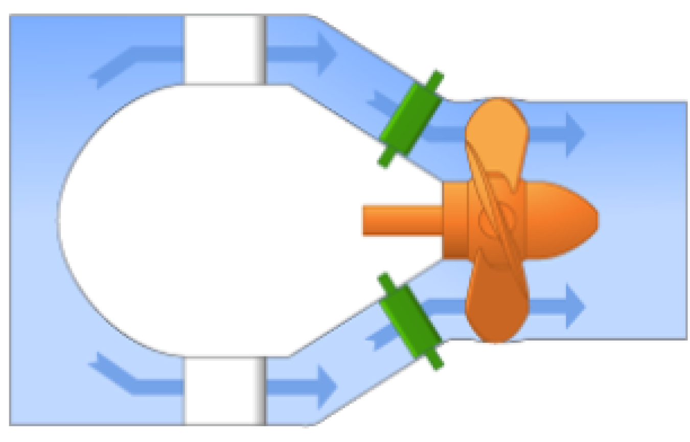
Bulb turbine: The turbine and generator are a sealed unit placed directly in the water stream.
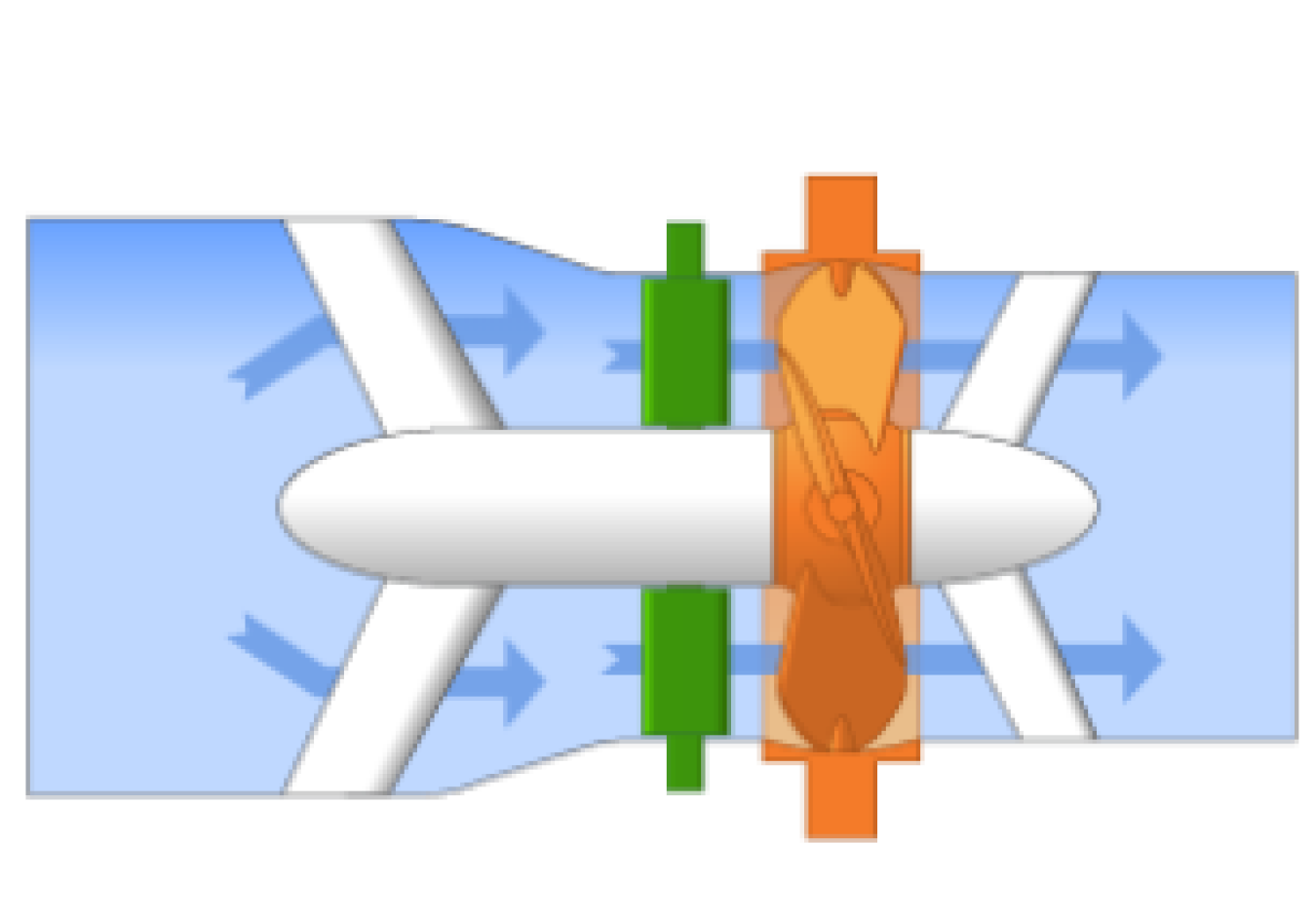
Straflo: The generator is attached directly to the perimeter of the turbine.
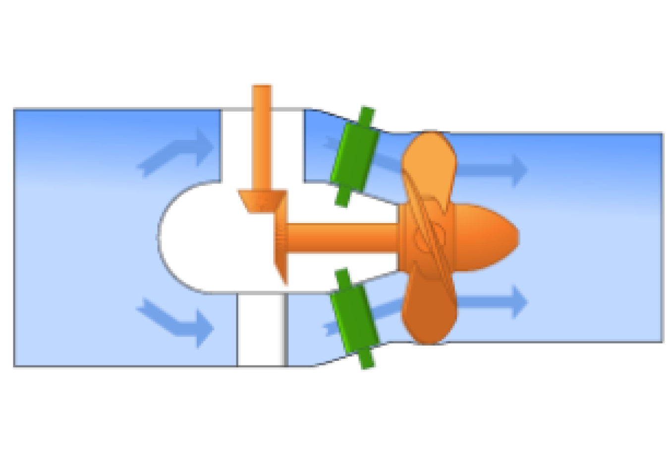
Tube turbine: The penstock bends just before or after the runner, allowing a straight-line connection to the generator.
Kaplan Turbine: Both the blades and the wicket gates are adjustable, allowing for a wider range of operation. This turbine was developed by Austrian inventor Viktor Kaplan in 1919.
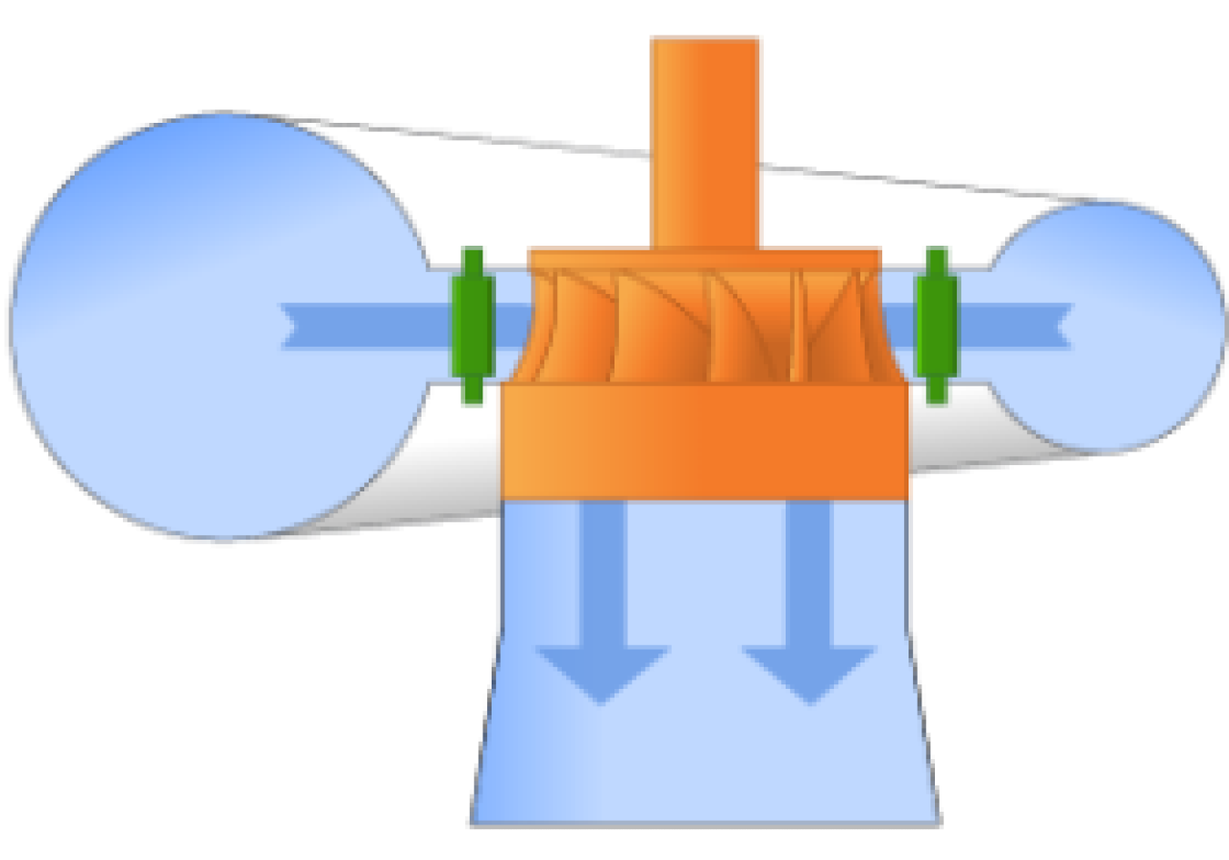
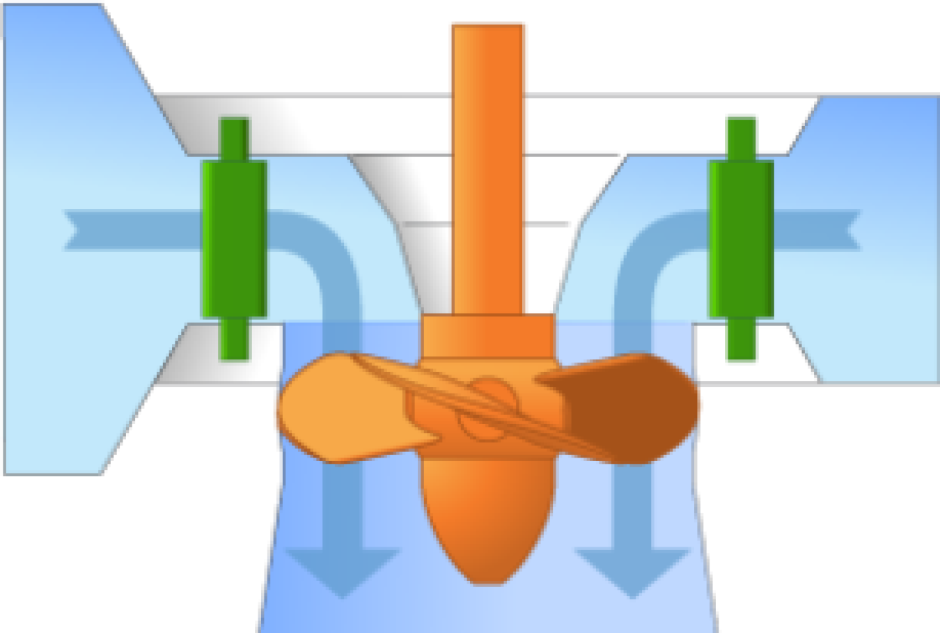
Francis Turbine: The Francis turbine was the first modern hydropower turbine and was invented by British-American engineer James Francis in 1849. A Francis turbine has a runner with fixed blades, usually nine or more. Water is introduced just above the runner and all around it which then falls through, causing the blades to spin. Besides the runner, the other major components include a scroll case, wicket gates, and a draft tube. Francis turbines are commonly used for medium- to high-head (130- to 2,000-foot) situations though they have been used for lower heads as well. Francis turbines work well in both horizontal and vertical orientations.
Kinetic Turbine: Kinetic energy turbines, also called free-flow turbines, generate electricity from the kinetic energy present in flowing water rather than the potential energy from the head. The systems can operate in rivers, man-made channels, tidal waters, or ocean currents. Because kinetic systems utilize a water stream's natural pathway, they do not require diversion of water through man-made channels, riverbeds, or pipes, although they might have applications in such conduits. Kinetic systems do not require large civil works because they can use existing structures, such as bridges, tailraces, and channels.
Impulse Turbine
An impulse turbine generally uses the velocity of the water to move the runner and discharges at atmospheric pressure. A water stream hits each bucket on the runner. With no suction on the down side of the turbine, the water flows out the bottom of the turbine housing after hitting the runner. An impulse turbine is generally suitable for high-head, low-flow applications. The two main types of impulse turbine are Pelton and cross-flow turbines.
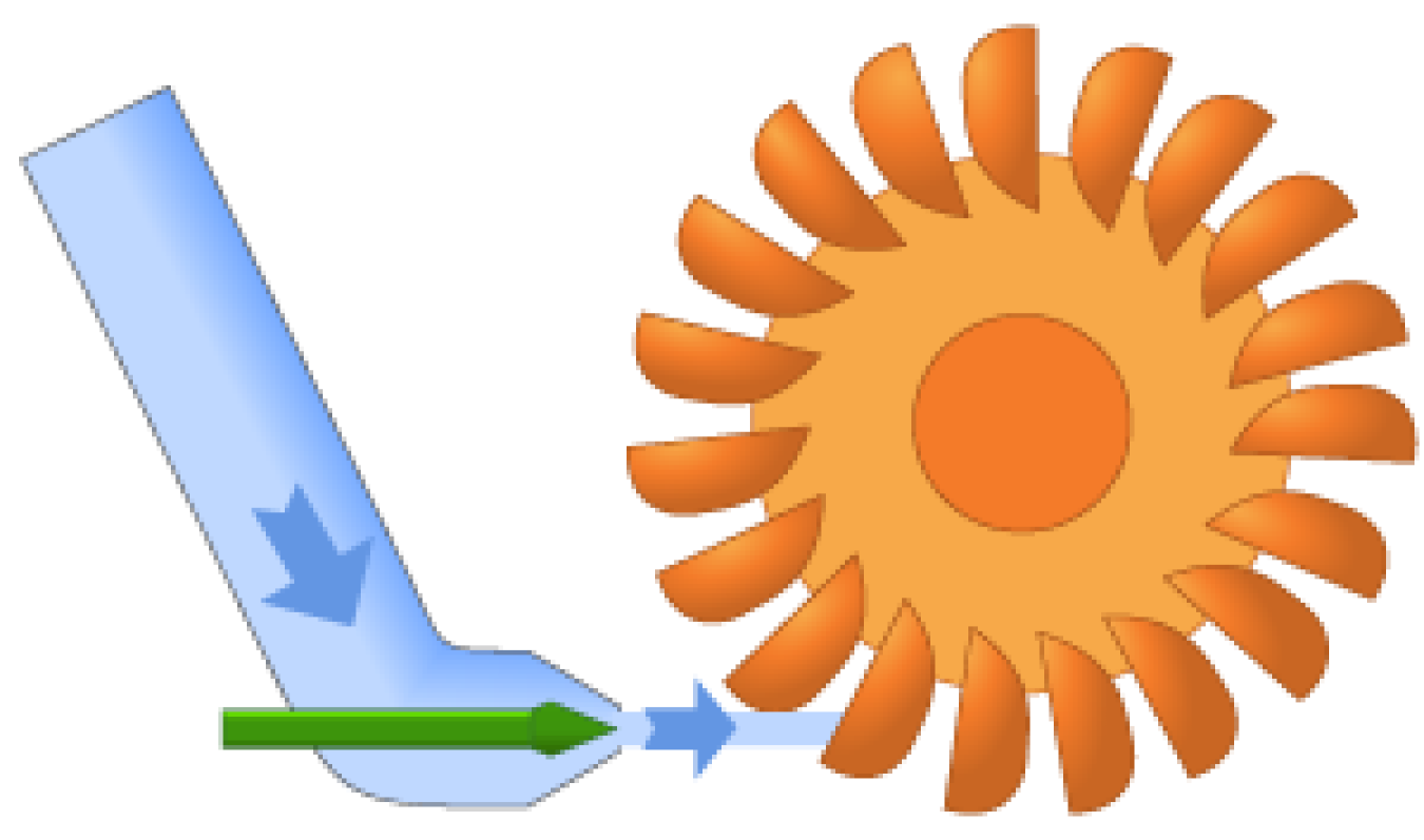
Pelton Turbine: The Pelton turbine was invented by American inventor Lester Allan Pelton in the 1870s, A Pelton wheel has one or more free jets discharging water into an aerated space and impinging on the buckets of a runner. Pelton turbines are generally used for very high heads and low flows. Draft tubes are not required for an impulse turbine because the runner must be located above the maximum tailwater to permit operation at atmospheric pressure.
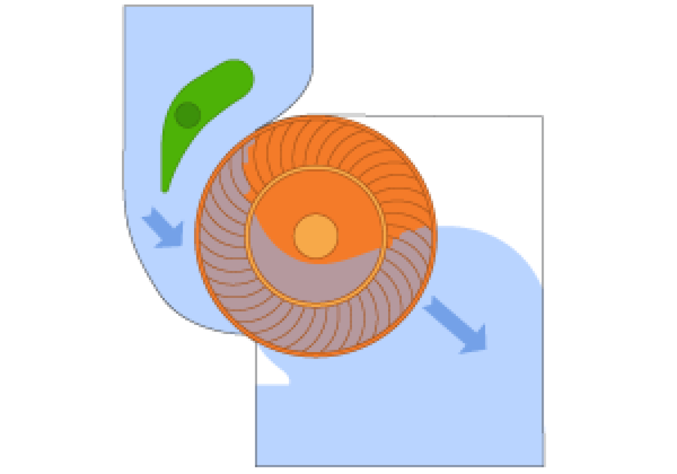
Cross-Flow Turbine: The original cross-flow turbine was designed by Anthony Michell, an Austrian engineer, in the early 1900s. Later, Donát Bánki, a Hungarian engineer, improved upon it, and it was improved even further by German engineer Fritz Ossberger. A cross-flow turbine is drum-shaped and uses an elongated, rectangular section nozzle directed against curved vanes on a cylindrically shaped runner. It resembles a "squirrel cage" blower. The cross-flow turbine allows water to flow through the blades twice. On the first pass, water flows from outside of the blades to the inside; the second pass goes from the inside back out. A guide vane at the entrance to the turbine directs the flow into a limited portion of the runner. The cross-flow turbine was developed to accommodate larger water flows and lower heads than the Pelton can handle.
Hydropower News
-
January 15, 2025
WPTO's Hydropower e-newsletter features news on R&D and applied science to advance sustainable hydropower and pumped-storage technologies.
WPTO brings funding opportunities, events, publications, & activities related to hydropower and marine energy directly to your inbox.